Design Calculation Centrifugal Fan Components. Low efficienc 69-75 at peak.
Centrifugal Fan Design Calculations Xls Solution By Surferpix
Radial centrifugal fans are rarely used in HVAC applications.
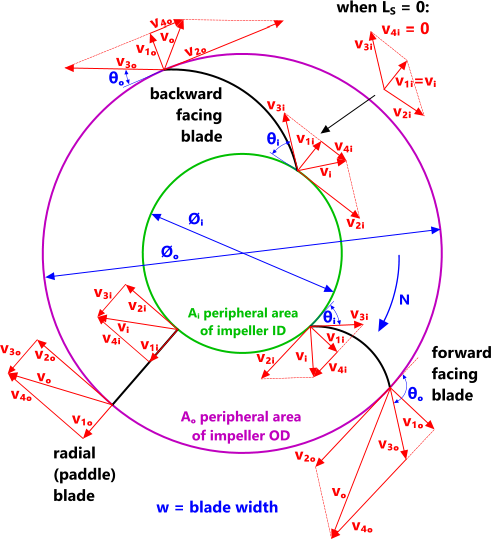
. Fans provides the most efficient blade inlet angle minimum inlet loss. Axial flow impulse fan with slotted flap adjustment shown during production. A Air capacity cfm varies directlywith fan speed.
Suitable for low air volume at high static pressure. Pics of. 4- Radial blades.
HP Volumecfm x Pressure psi 229 x Fan Efficiency. UL 705 Safety Testing. The usual pressure range of application is 0-76 mm water 0-745 pascals static pressure.
Ninth Edition - Edited by Robert Jorgensen. Assuming zero inlet swirl. For purpose of estimating the efficiency of a fan or blower may be assumed to be 065.
The flow is axial at entry and exit. Fan Engineering - An engineers handbook on fans and their applications. Free Impeller And Pump Design Software Miscellaneous Caeses Forum.
Factors which determine the performance of the fan include the number and shape of the blades. Centrifugal Fan Design Odologies. Generally 6 to 12 blades.
DESIGN OF AN AXIAL FLOW FAN FOR A VERTICAL WIND TUNNEL FOR PARATROOPERS submitted by FATİH ÇEVİK in partial fulfillment of the requirements for the degree of Master of Science in Mechanical Engineering Department Middle East Technical University by Prof. Calculations are provided for estimating fan power consumption and noise. Compact dimensions Choice of GreenTech EC or AC technology Many different designs sizes and air performance levels Optimum efficiency and minimal noise generation thanks to aerodynamically optimized fan blades Highly efficient energy-saving versions with GreenTech EC technology and standardized integration of control.
Impeller Design Of A Centrifugal Fan With Blade Optimization. Modeling A Damper Engineered Software Knowledge Base. Axial Centrifugal fan-blade design Whilst these calculation options are primarily for the performance characteristics of an impeller via blade configuration they also offer the performance effects of an external casing.
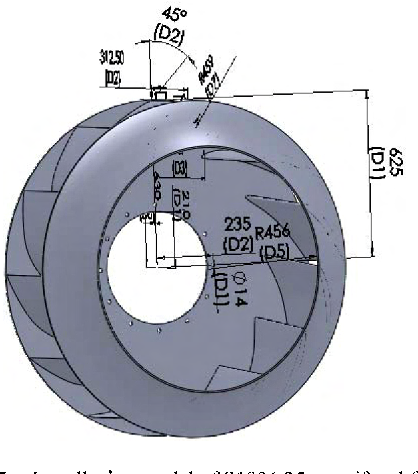
Simple in its design. Volume flow 660 m3s Temperature t 156 C Pressure increase p t 6520 Pa Speed n 590 1min Shaft power P Sh 5480 kW Diameter D 4220 mm Ø. Approval of the thesis.
Fan Laws and Fan HP Sizing Information from Fan Manufacturer Design Airflow CFM Design Static Pressure inches of WC Fan Speed Fan Motor Speed BHP Fan Power Fan Laws Table Airflow - CFM Static Pressure - in. We are pleased to be able to present the Ninth Edition of Fan Engineering which is recognised worldwide as THE definitive handbook on fan design and fan applications and reflects our lengthy experience with fan design. Centrifugal Pump Impeller Design Excel You.
Irp Cfturbo Design Of Impellers Various Types. Since the middle of the last century it has been pushing back the boundaries of axial flow design from its technology centre in Denmark Sweden and Germany Every fan we supply comes with a lifetime commitment to expert support. With applications for axial flow fans velocity recovery stacks seal discs and variable flow fans.
Centrifugal Fan Design Calculations Xls. THIS INFORMATION IS BEING MADE AVAILABLE SO THAT YOU CAN SEE HOW THE SPREADSHEET IS CALCULATING ITS INFORMATION AND TO GIVE YOU AN OPPORTUNITY TO CHECK OUR WORK. A first approximation for k is obtained by assuming ts efficiency of 60 and assuming that the static pressure rise at the average radius is equal to the fan static pressure.
Custom OEM Designs. The fan is designed to produce a pressure difference and hence force to cause a flow through the fan. Fan Motor Calculations Pulley Size Rpm Air Flow Rate Cfm Hvac.
Calculating axial fan ventilation fans. In order to cover uncertainties of the pressure drop calculation on one hand and. The calculation assumes a free vortex velocity profile downstream of the fan.
The vane axial and tube axial can be selected for higher outlet velocities than the centrifugal. Axial flow fans The performance of the axial flow fan is represented in figures A6 and A7 of Appendix A. Tunnel Fan Model Energy Efficiency Price of Fan Model Design static Tunnel Fan Number of fans Total air moving capacity Total fan operating pressure capacity required at design static pressure all fans operating Total Pad Area Pad water usage Five Year Ten Year Estimated Yearly Operating Hours per fan o Minimum Design Air Velocity ms House Length m.
Irp Effect Of Axial Gap Between Inlet Nozzle And Impeller On. Sheet Filename Title. Fan Data RPM Motor Sheave Dia Fan Calculation authored and generated by CTC Design Inc.
Flap adjustment on axial flow impulse fans are in many cases a simple means to meet specific operating conditions. Design validation was done by comparison with CFD analysis. Design Calculation Of Single Stage Radial Type Centrifugal Er.
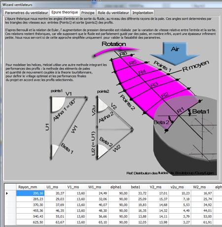
Our JV Partner Howden Axial Fans is the global centre of excellence for variable pitch axial flow fans. Dust Collection Research Er. The calculation and design of an axial fan for a blower or ventilation sytem aeraulic is to dimension the diameter of the fan the number of blades the speed of rotation the hub diameter and the twisting of the blades as a function of delta total pressure of the fan to be provided to compensate for pressure losses of the.
B Pressure varies with squareof fan speed. An axial fan is a type of fan that causes gas to flow through it in an axial direction parallel to the shaft about which the blades rotate. The main scope of the design process of an axial fans is to deliver high efficiency blades.
The facts at a glance. It should be noted that final fan selection should be made by using Hudsons Tuf-Lite Fan Selection Program or by contacting Hudson Products Corporation at 713-914-5700 or. The design of various elements of axial fan is discussed in detail.
Stall and operation range for an axial flow fan It has to be assured that plant resistance curve crosses the fan performance curve within that area. Their output data can be used for input in the Generic calculation option. The power characteristic is non overloading.
- 231 - 6thInternational Conference Tunnel Safety and Ventilation 2012 Graz Figure 2. A relation between volumetric flow and pressure is established with graphical approach which is a performance analysis. Fan Engineering has been written as a.

Download Fan Static Head Excel Sheet Calculator
Fan Design Calculator V1 Calqlata
Calculating Axial Fan Ventilation Fans
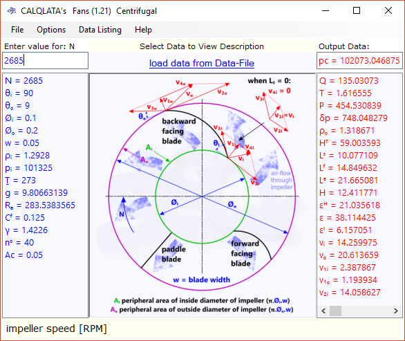
Fan Calculator Axial Centrifugal Pressure Flow Calqlata

Centrifugal And Axial Fans Selection Program Ahu Designer
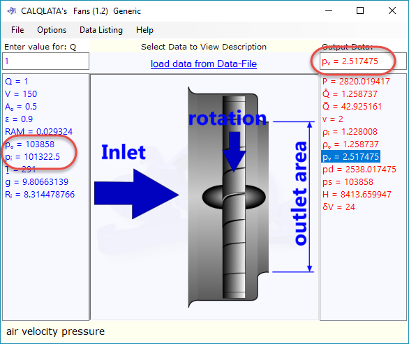
Fan Calculator Axial Centrifugal Pressure Flow Calqlata

Centrifugal Fan Design Calculations Xls Solution By Surferpix
Axial And Centrifugal Fan Software Ciclo Software
0 comments
Post a Comment